HSB Rekowagen

I’ve made a little progress with the Rekowagen. The main difficulty was how to do the windows, especially with my limited skills with a paintbrush!

I’ve settled on a raised edge around the window, then a recessed area, with the hopper further recessed. This means that I can airbrush the carriage, then use a silver pen to paint the hopper frame, followed by a black pen to line the rubber seal.

I then cut up 0.2mm glass microscope slide covers into 6mm squares, and glue these into recesses on the backs of the windows.

Here’s a picture of the current progress. This is a scrap part that I’m just using for testing the painting, but I think it’s nearly there. it just has a quick spray with primer, so the black window frames don’t show up that well in the photo.

IMG_20190604_123900951

Tomix Track Cleaner

Many years ago, I used to use a Tomix track cleaner a lot, not as a cleaner, but as a vacuum cleaner following the track cleaner around. This worked really well, until it was stolen at a show 😦

Now I have a nice track cleaner made from an MDS wagon, I thought I’d try and convert another Tomix cleaner for use on the Nm layout. It turns out, it’s quite easy.

IMG_20190510_124249281

The wheels can be squeezed along the axles in the same way as the MDS wagons. The centre spacer needs a little more clearance for the pickup parts on the Tomix wheels, and care is needed to press very straight, to not bend the thinner axles.

IMG_20190510_124221926

Once the axles are narrowed, the pickups need bending with a couple of pairs of pliers, and then the bogies can be screwed back on.

IMG_20190510_124129921_HDR

Still wondering whether to strip the paint, and put some RhB logos on 😉


MDS Track Cleaner

At Stuttgart, we always suffer with dirty track, and dirty wheels. We have a variety of track quality and cleanliness in the modular layout, and some of the rolling stock can be quite old and dirty too. Although we scrub the track regularly, during a four-day exhibition it keeps building up.

I decided to try and make a track cleaner from one of the nice MDS wagons. I already posted the method to narrow the wheels to run on 6.5mm gauge, but I then designed and printed a new chassis replacement which includes a pocket to carry an Aztec Cratex Roller track cleaner. This is a light abraisive roller, set at a couple of degrees to the track, so as it rolls, it produces a sideways scrubbing action.

IMG_20190426_122239474

IMG_20190426_122327005_HDR

I put the roller close to one end to try and keep it on both rails most of the time, even on tighter curves.

IMG_20190426_122301259

The File for the chassis part is here: https://www.thingiverse.com/thing:3589401

The wagons are made by MDS: mds-modell.eu

The Cratex Rollers are made by Aztec. Unfortunately, it seems they have gone out of business… That shows how slow I am at my projects! http://www.aztectrains.com/cratextrackclean.html  It might be possible to make something out of track rubbers with an axle, and turn it round in a lathe. Something to try when this one wears out.

MDS Wagons

The MDS range of wagons are now available, so I bought one at the Stuttgart show, with a view to re-gauging to Nm. Their product page is here: https://mds-modell.eu/produkte/baugroesse-n/wagen/

It’s not difficult, but the axles have one insulated wheel which moves easily on the axle, and one conductive which is very tight. Simply pushing the wheels together will only move the insulated one, and leave the wagon sitting off-centre.

Files to make the tool are here: https://www.thingiverse.com/thing:3278622

Here is a picture of the axle, before and after.

IMG_20181207_131424058_HDR

I printed a little spacer which is clipped onto the axleIMG_20181207_131455639_HDR

this assembly is then dropped into the tube, with the insulated wheel first.IMG_20181207_131525936_HDR

A 1mm hole drilled in a piece of 3mm thick aluminium sheet can press against the end of the axle without damaging it. The whole assembly is put into a G-Clamp, and carefully wound down.IMG_20181207_131630555_HDRIMG_20181207_131611418_HDR

This first press will move the insulated wheel along the axle, so that the back-to-back measures 5.4mmIMG_20181207_131706587_HDR

Now turn the axle round, put it back in the tube, and press it again until it has the same amount protruding from each end.

IMG_20181210_120926018_HDR

Some small notches are needed on the bogie to clear the muffs

IMG_20181210_121404826_HDR

Then re-assemble and it’s all done.

IMG_20181210_121450413

L45H Details

I managed to get my L45H nearly comleted for Stuttgart 2018, despite dropping the chassis on the floor 3 days before the show! Here are a couple of pictures of the current loco:

IMG_20181122_103348169_HDRIMG_20181122_103327674_HDR

I still have some detail painting to do, decals and handrails, but it’s almost there.

I’ve now uploaded all the files necessary to make a copy. You can find these on Thingiverse at:

Everything: https://www.thingiverse.com/thing:3261024

Chassis: https://www.thingiverse.com/thing:3255902

Window 2: https://www.thingiverse.com/thing:3255900

Window 1: https://www.thingiverse.com/thing:3255898

Body: https://www.thingiverse.com/thing:3255896

Weight Mould: https://www.thingiverse.com/thing:3255893

Tank Weight Mould: https://www.thingiverse.com/thing:3256012

Bogie Side: https://www.thingiverse.com/thing:3256024

I printed all of these on the Form2 at 0.05mm resolution. The windows were in clear v4, and everything else in grey v3.

The chassis takes all the parts from a Rokuhan Shorty Shinkansen chassis. To slow this down, I added 2 zener diodes and 220R resistor, following the instructions from Tom Knapp’s video: https://www.youtube.com/watch?v=1TPYGS0cxv0 . You will need to replace the fine wires on the power bogie with longer lengths.

The body is self-explanitory, but be very careful to not break the very thin window frames. These are fine after the windows have been added. Microtrains 905 couplers are added by tapping the small holes in the underside of the body 14BA.

The windows could be polished up perfectly clear, but I was ina  rush, so I just painted them in Johnsons Klear floor polish.

The weights are cast into the mould with Woods Metal. I found anything hotter doesn’t work well at all, with lost of distortion and outgassing. The main mould has centre marks to drill and tap 14BA to secure to the chassis.

The Rokuhan bogie sides can be carefully cut down with a knife and file, and then the bogie sides attached with eopxy adhesive.

The whole thing was primed with Halfords Plastic Primer, then painted with Weinert paints.


Kato Ge4/4II

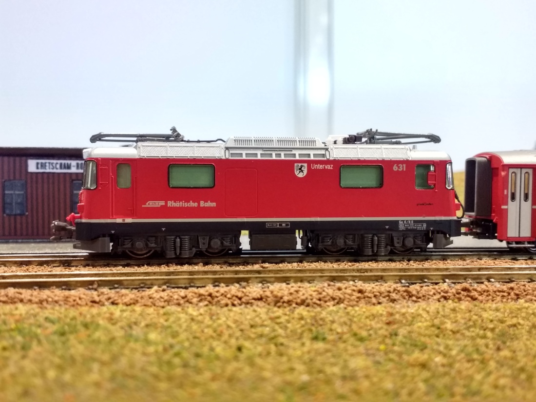
The Kato Ge4/4II is much harder to convert than any of the previous models. The axles on the idlers in the geartrain are just inside the diameter of the wheel flanges. This means that narrowing the mechanism enough to change to 6.5mm gauge will cut into the idler gears. My solution may not be the best way, but it is what works for me, and involves raising the whole unit by 0.5mm to provide enough clearance. The loco sits a little higher, but it’s not that noticeable in my opinion.

IMG_20181124_110755053_HDR

IMG_20181012_123847275_HDR

The method is more difficult than the other models, and requires more parts to be bought and made, so it’s best to know what you’re doing before starting work. Although this method works for me, I take no responsibility if it doesn’t work for you!

Parts and Tools

Method

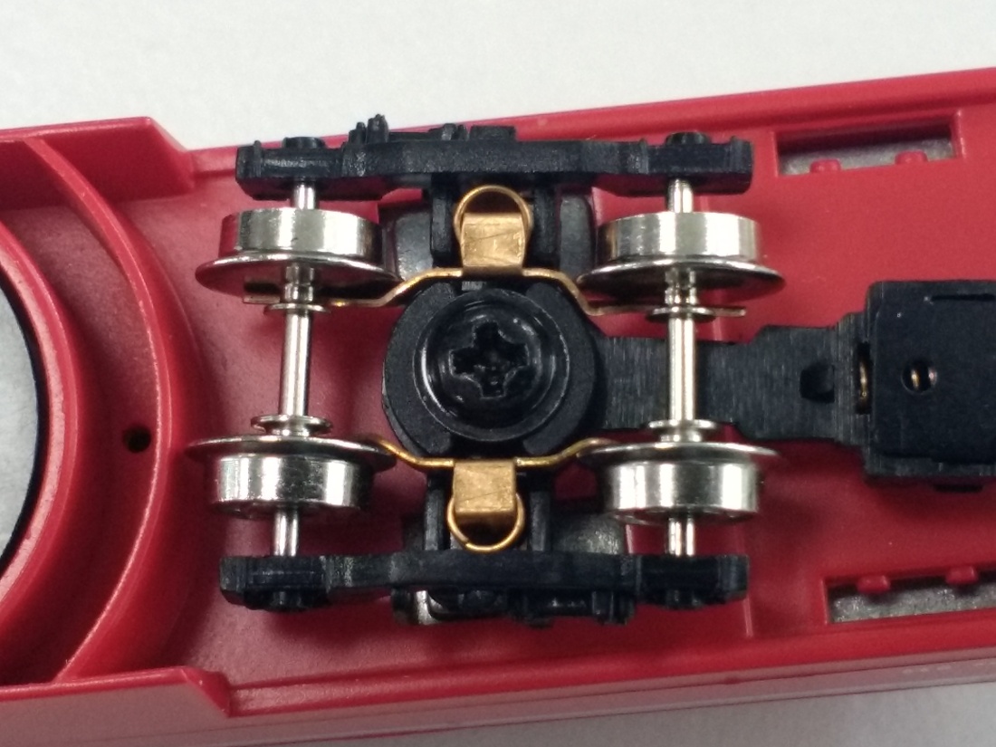
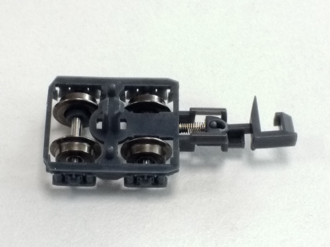
Start by dismantling the bogie. There are clips in each corner to release the central section, and then push it, along with the wheels, upwards from the bogie frame. The pickups will fall free, and then the wheelsets can be removed and set aside.

IMG_20181012_124200367

IMG_20181116_122446222_HDRCarefully spread the Gear Tower, and remove the three gears. Be very careful not to damage the gears themselves.

IMG_20181116_122652474_HDR

Axles

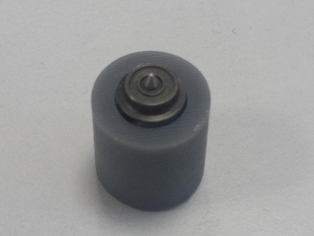
Pull each wheel and stub axle out of the black plastic gears.

IMG_20181116_122937451_HDR

Place a wheel in the multijig, and press down on the wheel to slide it along the axle. Repeat for all four wheels.

IMG_20181116_123020235_HDR

Push the wheels into the new 14 tooth gears, and check that the back-to-back measurement is 5.4mm with the multijig.

IMG_20181116_123334299

Check that the measurement across the points of each axle is 13mm.

IMG_20181116_124037472_HDR

Bogie Frame

Take the bogie frame and position it on the multijig. Drill through the jig to make two 0.8mm holes in the frame. Carefully countersink these holes to suit the 16BA screws.

IMG_20181116_124123935_HDRIMG_20181116_124310699_HDR

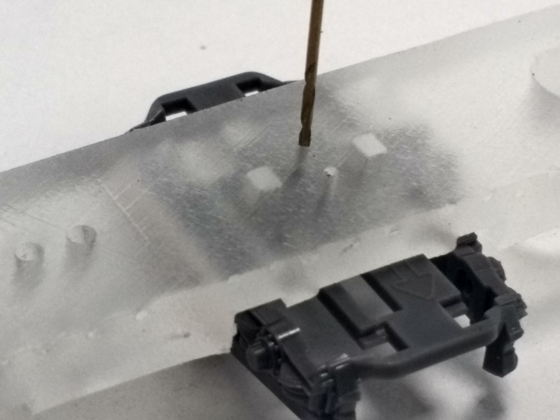
Now cut away the plastic base, leaving the central area and connection at both ends.

IMG_20181120_135727519_HDR

Re-assemble the bogie frame with both wheelsets and electrical pickups. It probably doesn’t matter which position the traction tyre is in within the bogie, but when re-assembling the loco they should be on opposite sides.

IMG_20181120_140038715_HDR

Gear Tower

Fit the end of the multijig to the side of the Gear Tower, and carefully drill a 0.8mm hole through. Repeat with the other side.

IMG_20181116_124948543

Take two 16BA countersunk screws, and cut them down using the multijig and flush cutters. File the ends clean with a needle file and check by screwing into a nut.

IMG_20181116_125422215_HDRIMG_20181116_125404814_HDRIMG_20181116_125830518_HDR

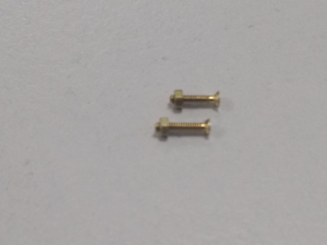
Take the Spacer Block and pass the Cheese Head screw through one of the holes, fitting a plain washer. Thread a 16BA nut onto the screw, and then tighten to pull the nut into the hexagon pocket. Remove the screw, and repeat with the other hole.


Fit the Spacer Block to the Multijig using the two countersunk screws cut down previously.

IMG_20181119_121643497_HDR

Check that the empty Gear Tower fits over the Spacer Block, and sits right down onto the jig.

Apply Cyanoacrylate Activator to both sides of the Spacer Block, and also the mating faces on the inside of the Gear Tower.

After allowing the activator to dry for a minute or so, apply a thin spread of Cyanaoacrylate glue to the sides of the Spacer Block, and then slide the Gear Tower over until it is firmly pressed against the multijig. Allow plenty of time for the glue to fully harden before moving on to the next step.

IMG_20181119_121709100_HDR

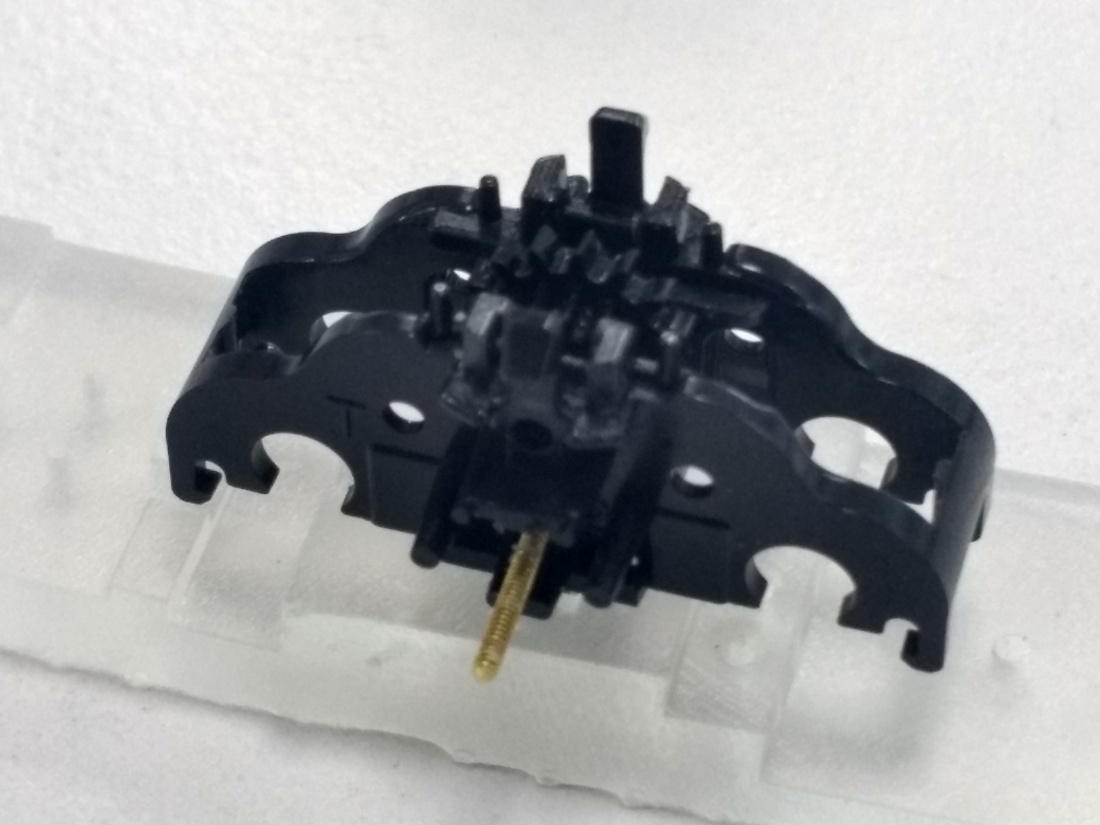
Using a 0.8mm Jewellers Cutting Broach, gently open the hole right through the Gear Tower and Spacer Block assembly, until the 16BA Cheese Head Screw just fits through.

IMG_20181119_122236418_HDR

Apply a small smear of Threadlock to the screw, and then run a nut along the thread until it is fully home, but do not tighten. This screw will provide support when the two sides of the Gear Tower are spread apart to fit the gears, otherwise the CA glue will fail very easily.

IMG_20181119_123040687_HDR

Gently fit the central gear, noting that it will only fit one way round. If you feel the glue crack, dismantle the assembly, clean it up and start again.

Tighten the 16BA screw while turning the central gear, until it starts to bind, then back off the pressure so that it is free to spin again. Leave the assembly for a while for the threadlock to harden.

With flush cutters, nip off the long end of the screw.

After everything is dry and fully hard, remove the two countersunk screws holding the assembly to the multijig.

Cut the ends off the Gear Tower using Flush Cutters facing away from the Spacer Block, to avoid any shock to the glued joint.

IMG_20181119_123431430_HDR

Fit the end of the multijig over one side of the gear tower, and cut the plastic back to the edge of the jig. TAKE GREAT CARE HERE. The cut is very close to the axle hole for the idler gear, and this should not be distorted. Do not be tempted to cut too much away in a  single cut: take several small cuts until reaching the final shape.

IMG_20181119_123709738_HDR

Check that there is no excess glue at the joint of the Gear Tower and Spacer Block. If there is, then gently remove it with a scalpel.IMG_20181119_124306681_HDR

Gently re-fit the idler gears to the Gear Tower, and check that everything spins freely.
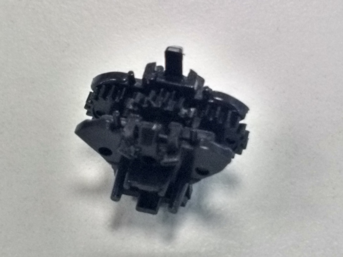
IMG_20181119_124953434_HDR

Assembly

Fit the Gear Tower into the Bogie Frame.

Apply a small smear of Threadlock to the two 16BA Countersunk Screws. Fit the two 16BA Countersunk Screws through the holes in the Bogie Frame, and into the Spacer Block. Be careful not to push the nuts out of their holes. Tighten the screws while checking the mesh of the whole geartrain.

IMG_20181012_123910419_HDR

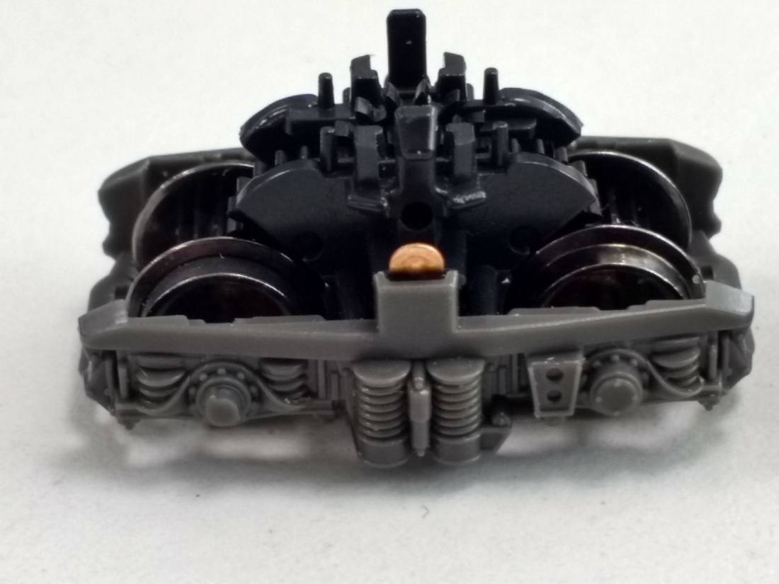
Everything should be free to rotate, with no tight spots or cogging. If there is, then dismantle the assembly and try again.

Fit the bogie into a loco and give it a test run! I modified two locos and ran them for all four days of Modellbahn Süd 2018, and everything went well. They ran smoothly and capable of very low-speed crawling, even the one which used the first bogies I modified, which were rather tight.


Casting into Formlabs moulds

I’ve made a little progress on the L45H, after being ripped off by two different sellers on eBay for Woods Metal. I made a CAD model of the inside space of the loco, then used this to make a mould with 0.5mm walls. I printed this on the Form2, and tried casting metal into it, with varying results.

I first tried using traditional 60/40 Tin/Lead solder, and found two big issues. The thermal shock of pouring the metal into the mould was causing it crack, and lots of gas was released from the SLA material. What I got, was poor surface finish, with lots of trapped bubbles.

I tried again with Prince August casting metal, but got much the same results. This metal has less viscosity, so flowed into the mould better, but still produced poor parts.

I finally tried Woods metal, which melts at 70°C. I warmed up the mould in hot water first, then poured in the metal, leaving it in the hot water bath to slowly cool. The mould survived this shock fine, and the metal produced really fine detail, even down to the step lines in the 3D print. Unfortunately, the mould distorted due the thermal expansion and forces from the weight of material, so I had to file it up a bit afterwards. Something to remember for next time would be to put some ribs on the outside to stiffen it up.

So I now have a weight for the L45H. It needs a little more tweaking, then I can sort out the wiring, and that should just leave the painting to do. I visit the Fichtelbergbahn in August, so I’ll take a paint chart and try and work out what colours to use.

Updates

Sorry there hasn’t been any updates for a while, but I’m working on many different projects, with not much to show anywhere.

The L45H is almost finished, but I’ve been waiting for a delivery of some wood’s metal to make the weight before going any further. I’m also finding it difficult to work out what paint to use.

I’ve spent a lot of time trying to convert the 4/4II bogies. These are much harder than any of the others so far, as the idler gear axles are in the way when narrowing the block. I’ve tried four different ideas so far without success. I’m now planning to try raising the whole assembly a little to provide clearance, and using larger gears on the axles to compensate. The body will sit 0.3-0.5mm higher, but I don’t think it’s too noticeable. The only problem is that KKPMO are on holiday, so I have to wait until I can get some more gears.

I’ve started work on an ÖBB 2095 diesel, based on my experiences with the L45H. I have a test chassis and bogies waiting to be built, but the difficulty here is the external cranks and coupling rods. I hope to have something running in the next few weeks, and then start looking at the body. The plan is to have something in time for TINGS to run on Rudolf’s Klaus an der Phyrnbahn.

So I’ll keep on going, and hope to have something to show in the near future.

L45H

The L45H is nearly finished, but still has a few niggles to sort out. I also plan to make some bogie sideframes to glue over the Rokuhan ones to make it look better. Here is a picture of it at the ESNG show last weekend:

IMG_20180414_094716572_BURST001

There’s also some little videos of it running on Mark Fielder’s Pizza layout: